







As machines get smaller and production floor space gets more expensive, engineers and procurement teams are re-evaluating the traditional architecture of a servo drive in the control cabinet connected to a remote motor by multi-conductor cables. An integrated servo motor combines drive, motor, encoder, and communication interface into one housing. Some variants extend the integration further, combining the integrated servo motor and controller in a single unit so that motion logic runs on board without an external PLC axis card.
The trade-offs are not one-sided. This article compares the two architectures across five dimensions.
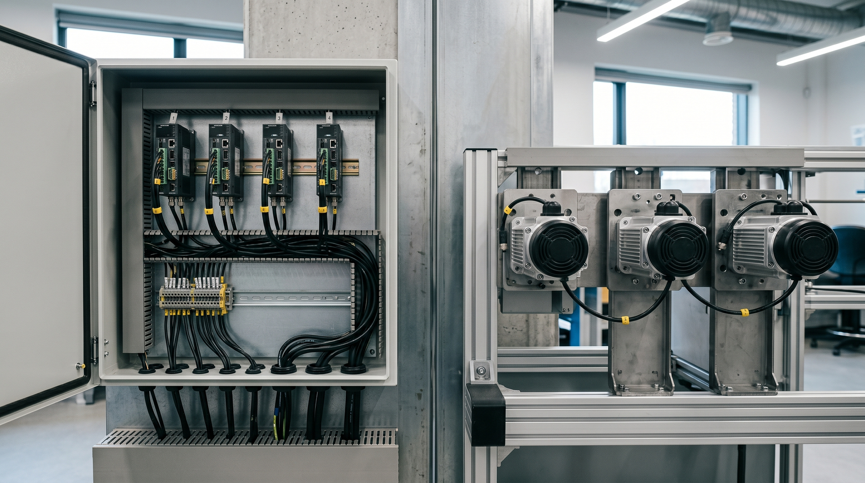
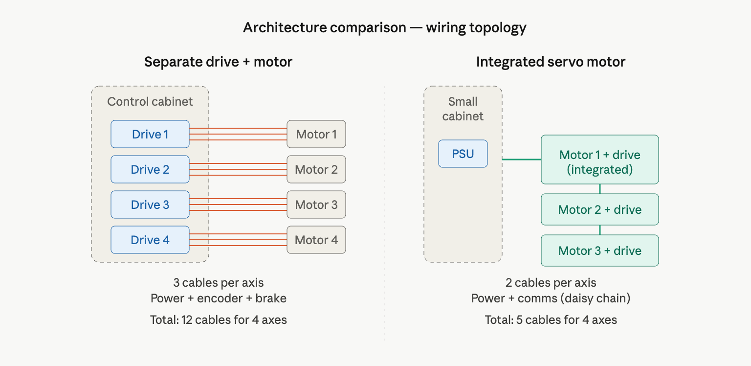
Moving the drive electronics out of the cabinet eliminates one drive slot per axis. For a 4-axis machine, this typically translates to 160 to 320 mm of cabinet width recovered, depending on drive form factor.
In a separate setup, each axis requires a drive slot in the cabinet (typical width 40 to 80 mm per drive), plus cable routing space, heat dissipation clearance, and DIN rail or mounting hardware. The cabinet also needs cooling capacity sized for the total drive heat dissipation.
In an integrated setup, the drive moves out of the cabinet entirely. For a 4-axis machine with 60 mm-wide drive modules, this recovers roughly 240 mm of cabinet width, plus the cooling and cable-routing clearance around each drive. As coverage in Manufacturing AUTOMATION notes, the consolidated design also simplifies the bill of materials and frees space for non-motor components such as sensors, material handling mechanisms, and operator interfaces.[1]
The practical limit is power. An integrated servo motor and drive unit is typically available up to 400W to 750W per axis. Applications requiring 1 kW or higher per axis still use the separate architecture, because the drive electronics for those power ratings cannot fit in the motor housing.
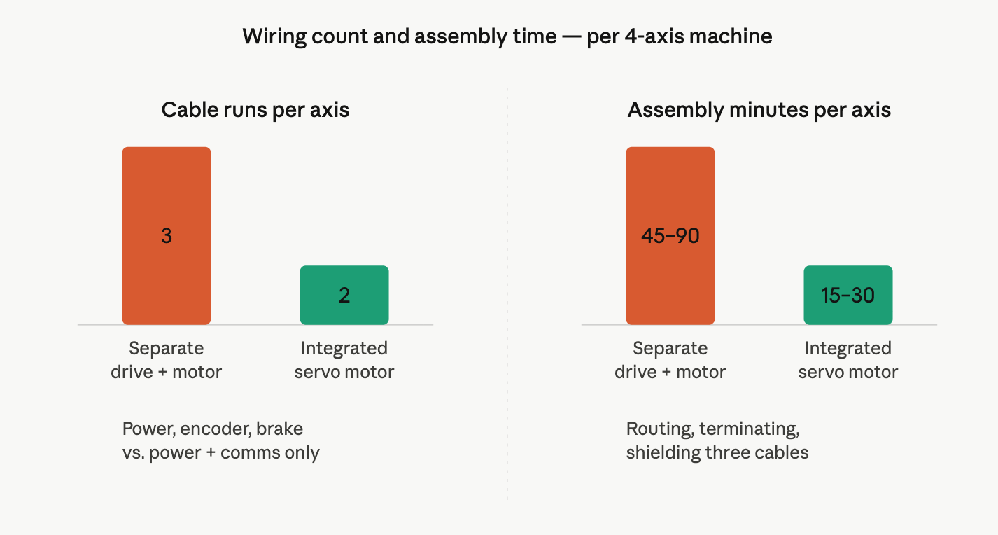
Wiring reduces from three cable runs per axis to two. For a 6-axis machine, this typically saves 3 to 6 hours of assembly labor.
In a separate setup, each axis requires:
A motor power cable (typically 4-conductor plus shield)
An encoder cable (6 to 12 conductors depending on feedback type)
A brake cable when a holding brake is used
Each run requires routing, strain relief, shielding termination, and connector assembly. The encoder cable in particular demands attention to grounding and shield termination to avoid electromagnetic interference.
In an integrated setup, each axis needs only:
One communication cable (EtherCAT, CANopen, or RS-485, daisy-chained between motors)
One DC power cable
Beyond labor, fewer cables means fewer failure points. Cable breakage, connector corrosion, and EMI-induced encoder faults are common service issues in machines with long flex life or harsh ambient conditions.[1]
The drive electronics inside an integrated servo motor share the motor housing, so they operate closer to the motor's heat source. The thermal trade-off is real but rarely a practical problem below 40°C ambient.
In a separate setup, the drive sits in a climate-controlled cabinet, protected from dust, moisture, and thermal cycling. The motor operates in the field environment but generates less heat because drive-stage losses are remote.
In an integrated setup, the drive's power-stage losses are dissipated through the same aluminum housing that conducts motor heat. Modern integrated servo motors use finned aluminum housings for passive cooling, and most are rated for continuous operation up to 40°C ambient without derating.
The applications where integrated servos are most often deployed (packaging, labeling, light assembly, electronics manufacturing) typically operate below 35°C ambient. Foundries, bakery ovens, and other high-heat environments are where the separate architecture retains a clear advantage.
In a separate setup, a failed drive can be swapped in the cabinet without disturbing the mechanical assembly. In an integrated setup, the entire motor-drive unit must be removed from the machine, which can require mechanical re-alignment after reinstallation.
This is the most common counter-argument against integrated servo motors. For machines in continuous production where downtime cost exceeds USD $500 per hour, the ability to swap a drive in 10 minutes versus replacing an entire motor unit in 30 to 60 minutes is a meaningful difference.
The counter-counter-argument is failure frequency. Integrated servo motors and drive units have fewer external cable connections, which means fewer points where vibration, flexing, or corrosion can cause faults. Each time a cable bends or flexes, its copper conductors and shields are mechanically stressed, and W. L. Gore & Associates documents this as a direct contributor to reliability problems in high-flex automation environments.[2] In cable carriers, robotic arms, or food and beverage washdown environments, cable-related failures often outnumber drive electronics failures.
The decision depends on which failure mode is more common in the target application. Maintenance records from comparable machines are the best source of data for this judgment.
The integrated unit price is higher than a standalone motor of the same power rating, because it includes drive electronics. The total system cost is lower when the count of axes reaches three or more.
The cost categories that shift between architectures:
Cost item | Separate | Integrated |
Motor + drive component cost | Lower | Higher |
Motor power cable | Required per axis | Not required |
Encoder cable | Required per axis | Not required |
Cabinet size | Larger | Smaller |
Cabinet cooling | Higher BTU/h | Lower BTU/h |
Assembly labor | 45 to 90 min per axis | 15 to 30 min per axis |
Shipping volume | Larger | Smaller |
For OEM machine builders producing the same design in volume, the labor savings alone often justify the integrated architecture. The space and shipping savings compound when machines are exported in containers where volume is metered.
The break-even point depends on local labor rates, cabinet costs, and axis count. A reasonable rule of thumb: at 3 or more axes per machine, integrated systems usually have lower total cost; at 1 to 2 axes, the choice depends on specific application priorities.
The architecture choice resolves to four questions about the application:
Application factor | Choose integrated | Choose separate |
Power per axis | ≤ 750W | > 1 kW |
Cabinet space | Constrained | Available |
Ambient temperature | Below 40°C | Above 40°C or harsh |
Service preference | Few external cables | Drive-only field swap |
Production volume | OEM mass production | Custom, low-volume |
For applications that match the integrated profile, Leadshine offers the iSV2 Series integrated servo motors, available in CANopen and Modbus RTU/Pulse variants with power ratings from 200W to 750W and frame sizes from 60 mm (NEMA 23) to 80 mm (NEMA 34). Both variants support 24 VDC and 48 VDC input, with optional holding brake configurations.
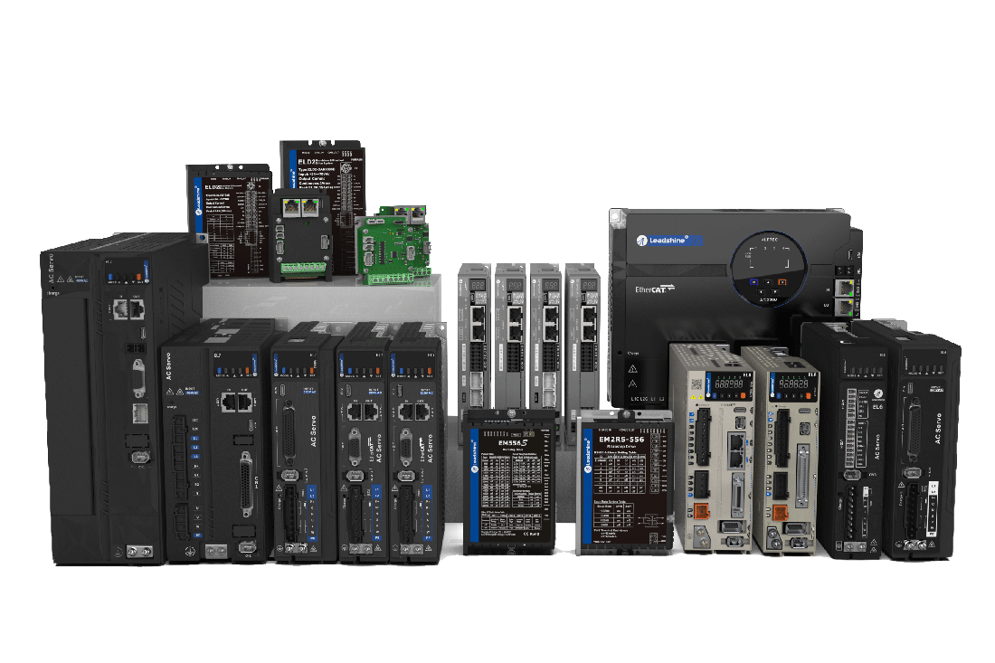
For applications outside the integrated profile (higher power, harsh environments, or service workflows that require swapping the drive alone), the separate architecture of servo drives and motors using EL7 or EL8 servo drives paired with Leadshine AC servo motors covers power ranges up to 7.5 kW with full safety certification including STO SIL3.
For configuration assistance, application-specific sizing, or quote requests, Leadshine's technical support team provides direct engineering support.
References
1. "Integrated Motors 101." Manufacturing AUTOMATION, 28 July 2021, www.automationmag.com/integrated-motors-101.
2. "Tech Note: Understanding Cable Stress and Failure in High Flex Applications." W. L. Gore & Associates, Inc., gore.com/node/4396.